Case Study: Sourcing Custom Cylindrical Floor Scrubbers for Rubber Running Tracks
- Industry
- Commercial cleaning equipment
- Application
- School rubber running track (textured, uneven, elastic surface)
- Scope
- Batch production for a European facility project
- Service
- PIMOLINK — Sourcing & Coordination
The Challenge
The buyer needed cylindrical floor scrubbers for a school rubber running track project.
Standard scrubbers are designed for smooth, continuous surfaces — epoxy floors, polished concrete, cement. Rubber tracks are different: textured surface, elastic deformation, micro-gaps, and local height variations.
Three specific challenges emerged when suppliers said "Yes, we can customize."
Challenge 1: Squeegee System — The Hidden Air Leak Problem
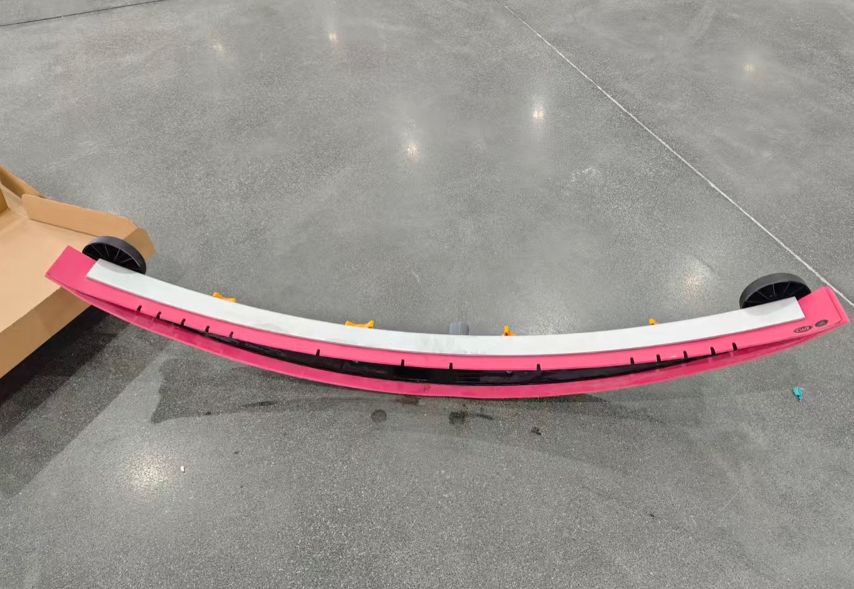
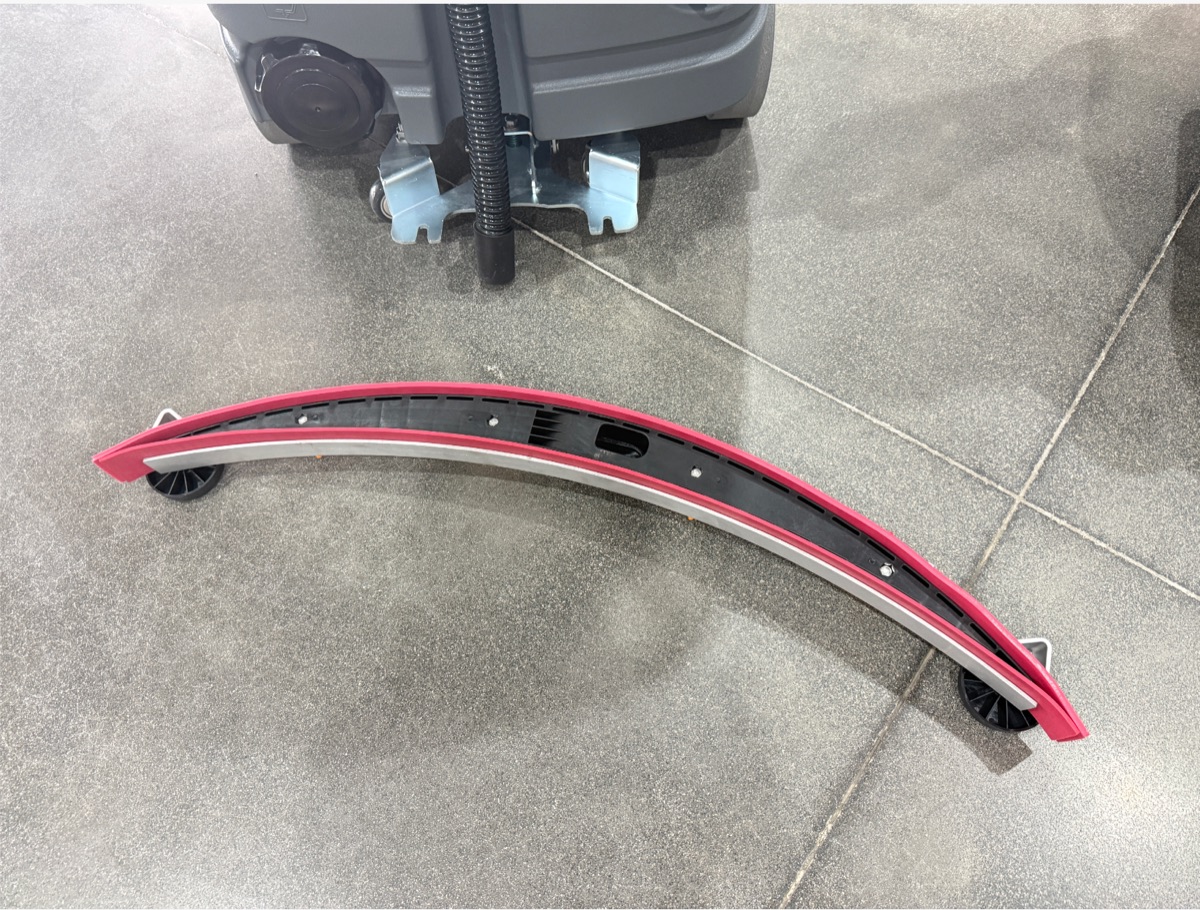
Standard scrubbers use a dual-squeegee system:
- Front squeegee (with holes) — wastewater enters the suction chamber
- Rear squeegee (solid, no holes) — seals the chamber
- Vacuum motor extracts the water
| Front squeegee (holes) | Rear squeegee (solid) |
|---|---|
|
|
On smooth surfaces (epoxy, concrete, polished floors), the rear squeegee lies flat and seals perfectly. On rubber running tracks, the problem appears:
The textured surface creates micro-gaps between the squeegee and the ground. Air leaks in, the vacuum loses suction, and water stays on the track.
The solution we developed: a custom solid (no holes) rear squeegee — not to block water from entering, but to reduce air leakage paths on the uneven surface and maintain stable suction pressure.
This is not a standard part. It requires understanding the physics of airflow on irregular surfaces.
Challenge 2: Brush Pressure Adjustment — From Preset to Programmable
Some commercial scrubbers support brush pressure adjustment, but typically it's limited to preset levels: Low / Medium / High, or Level 1 / 2 / 3.
The buyer needed something different: independent adjustment on-site. The end-user must be able to fine-tune the pressure themselves, not choose from fixed presets.
Why this is technically challenging
Step 1 — How brush pressure is actually measured:
- Brush meets resistance from the ground
- Motor load increases
- Current changes (amps)
- Controller interprets the current change
- Pressure is estimated (not directly measured)
Surface friction creates a resisting torque at the brush.
The motor must overcome the resisting torque.
To maintain the target speed, the motor produces more torque.
The controller uses current as an indirect load / pressure signal.
The operator adjusts the preset level while protection limits guard the motor.
So the controller must support:
- Current monitoring
- Current adjustment
- Parameter setting
- Protection limits (to prevent motor burnout)
Step 2 — User interface for on-site adjustment:
Many factories can change parameters only in the factory, with a laptop connected to the controller. But the buyer needed to adjust on-site, without an engineer. So we required:
- HMI display (user interface)
- Parameter menu
- User enters: brush pressure setting
- Adjusts current: X A → Y A → Z A (site-specific — final values are set during on-site calibration, not fixed at the factory)
- Saves the new parameter
- Machine operates with the new setting
This moves beyond simple customization into semi-customized control system development — something most factories are not equipped to handle. The question is not "Can you adjust it?" The question is "Can the end-user adjust it, safely and independently?"
Challenge 3: Brush System — Softness + Counter-Rotation
| Requirement | Why it matters |
|---|---|
| Soft cylindrical brushes | Rubber surfaces damage easily with hard bristles |
| Counter-rotating brushes | Effective cleaning on textured ground |
| Custom brush configuration | Must match the specific rubber track material |
These requirements are relatively straightforward compared to the first two — but they still needed verification on the actual surface, not just in the factory lab.
The Process
Here is the step-by-step workflow we followed to verify and deliver this project.
-
Step 1 — Application Analysis
- Rubber track surface: textured, elastic, uneven
- Identified: squeegee air leakage + pressure control gaps
-
Step 2 — Supplier Screening (5 suppliers → 1 shortlisted)
- Asked technical questions (not just "Can you do it?")
- Filtered out those who couldn't explain the solution
-
Step 3 — Technical Development
- Factory developed current-based pressure adjustment
- Custom solid rear squeegee designed for textured surface
- HMI interface added for on-site user adjustment
-
Step 4 — Parallel Verification (On-Site + Platform)
On-Site (Human)
- Brush rotation & softness test
- Pressure adjustment range (20A–30A)
- Squeegee air leak test on uneven surface
- Full system integration check
PIMOLINK Platform (Data)
Supplier uploads:
- Production progress
- Technical specs & drawings
- Packaging dimensions
- Accessory quantities
- Customs documents
- Shipping marks & labels
Buyer views the dashboard in real time and tracks every detail.
- PIMOLINK cross-verifies: human check + system data = full match
- PIMOLINK takes full responsibility for all details
- All data is tracked and archived for future traceability
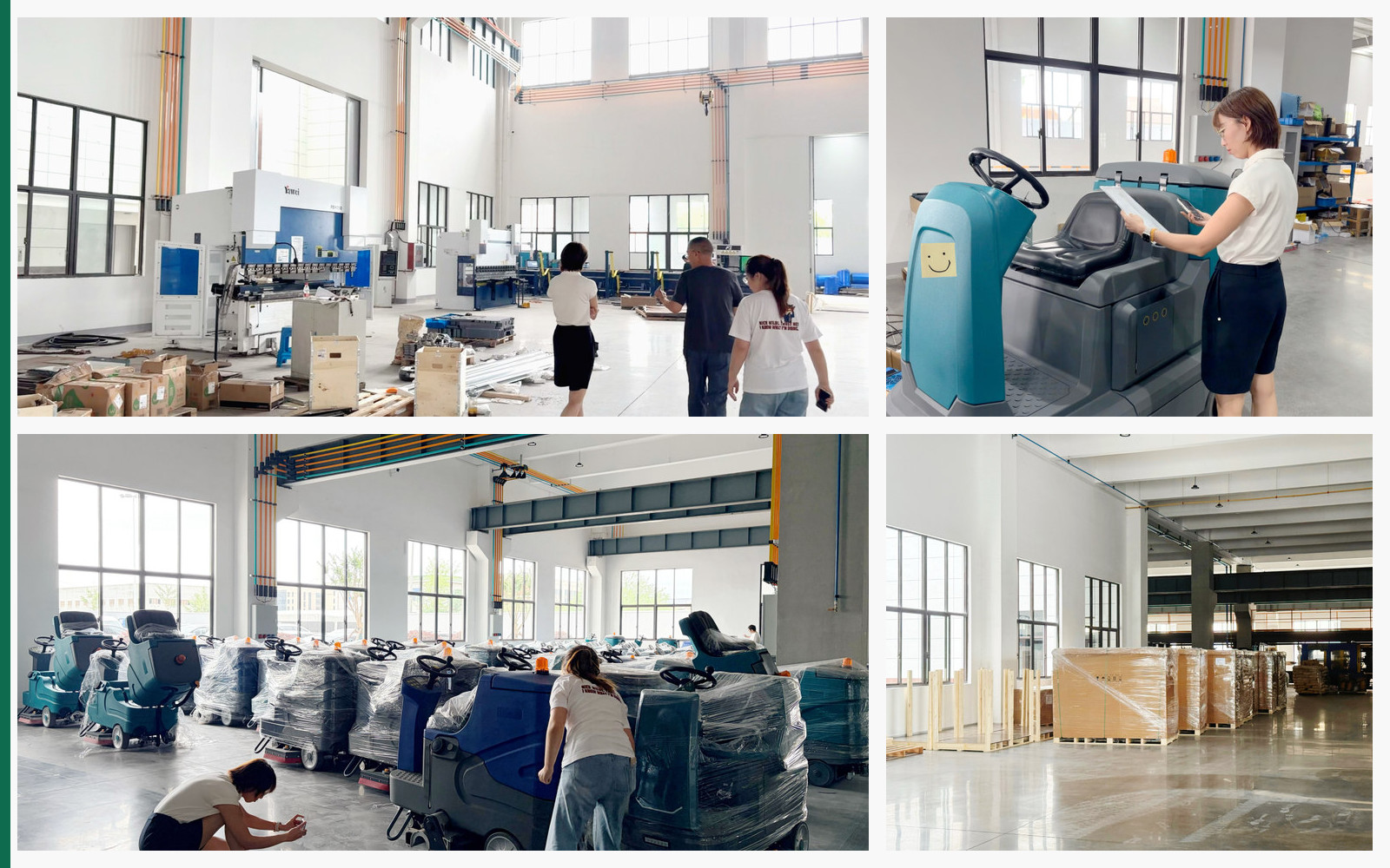
On-site factory verification: facility review, machine inspection, specification checks, and packed-unit confirmation. -
Step 5 — Final Review & Delivery
- All platform data verified against physical inspection
- Batch production approved
- Consistent quality across all units
- Full digital record archived for buyer
What We Verified On-Site
| Category | Specific checks |
|---|---|
| Squeegee system | Air leakage on textured surface, suction stability, water recovery rate |
| Pressure control | Current adjustment range (20A–30A), HMI interface, motor safety limits |
| Brush system | Rotation direction, softness level, counter-rotation configuration |
| Full system | Squeegee + brush + pressure working together on uneven simulation |
What We Verified at the Factory
| Category | What we checked |
|---|---|
| Molds | Factory owns the molds — future replacement parts are secure |
| Rotomolding | Tank wall thickness, material consistency |
| Metal fabrication | Welding quality, frame alignment |
| Rust protection | Electrophoretic coating — not just spray paint |
| Packaging | Wooden frame, bolt-down fixation, moisture barrier for sea freight |
| Documentation | Manual, labels, and certificates match the customized specs |
The Outcome
- Customized scrubbers delivered on schedule
- All batch units met the same quality standard
- End-user can adjust brush pressure on-site via HMI (20A–30A range)
- Solid rear squeegee maintained suction on textured rubber surface
- Machines performed effectively on the actual track
The selected supplier was not the cheapest. They were the one who could explain the physics and prove the process.
Key Takeaways for Buyers
A supplier's "Yes" is only the beginning. Ask the technical questions:
- How does the pressure adjustment actually work?
- Can my end-user adjust it on-site?
- Does your squeegee design account for my surface texture?
Customization is not a one-off promise. It is a repeatable process that connects:
Let's Talk About Your Project
Have a commercial equipment project with specific application requirements? Contact PIMOLINK and we'll help you navigate supplier selection, customization verification, and quality control — all on the ground in China.
info@pimolink.com · rebecca@pimolink.com · www.pimolink.com
Talk to Our Sourcing Team